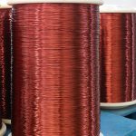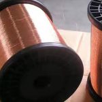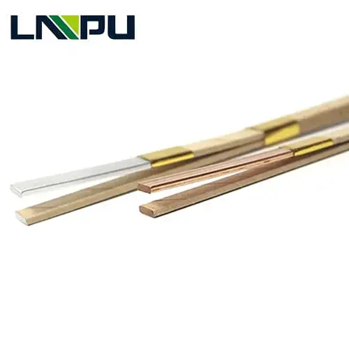
Match your transformer winding copper wire to the electrical design, available winding space and insulation system. Explore seven-strand CTC, five-strand CTC and paper-covered enameled round copper configurations, with clearly defined dimensions and ordering requirements.
Send your conductor drawing, insulation specification and required continuous lengths to request a quotation. Confirm the proposed construction, inspection documents and delivery schedule before placing an order.
Request a Technical Quotation | Submit Your Winding Specification
What Is Transformer Winding Copper Wire?
Transformer winding copper wire is an insulated copper conductor used to form transformer windings and carry their electrical current. Its specification combines copper geometry, electrical properties, mechanical condition and insulation construction.
A complete conductor specification includes more than a bare wire diameter or copper cross-section. Finished dimensions determine winding fit, while insulation and mechanical properties influence processing and performance within the approved transformer design.
This page describes three reference configurations: seven-strand continuously transposed conductor, five-strand continuously transposed conductor and paper-covered enameled round copper wire. The configurations come from engineering inquiry specifications. Their values represent requested design requirements, rather than independently verified production results or general stock availability.
Use the examples to prepare a detailed purchasing specification. Final suitability depends on the transformer design and an agreed technical review, including operating conditions, dimensional limits and acceptance criteria.
How Continuously Transposed Conductor Works
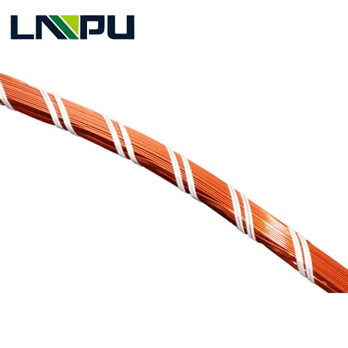
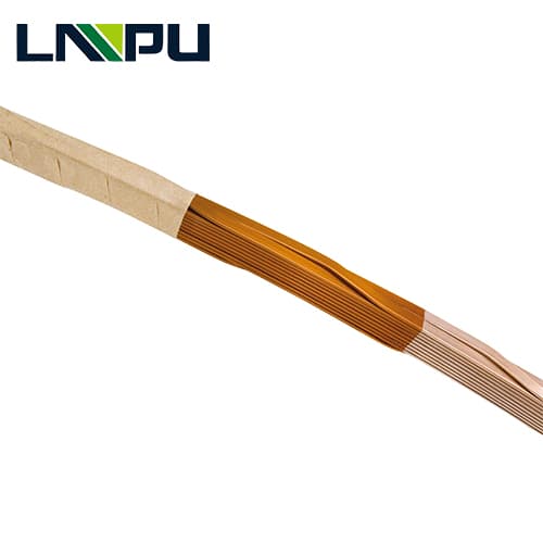
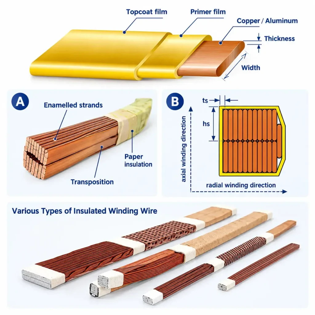
Continuously transposed conductor, or CTC, combines individually insulated copper strands that change position along the conductor length. The strand arrangement creates a shaped bundle for transformer winding.
Parallel strands can experience different magnetic conditions when their positions remain fixed. Transposition helps balance their exposure, addressing unequal induced voltages and associated circulating currents in suitable winding designs.
The construction follows three functional principles:
- Individual strand insulation: Enamel electrically separates adjacent copper strands.
- Controlled strand transposition: Each strand follows a defined positional sequence along the bundle.
- External insulation: Paper wrapping provides the specified outer covering and contributes to finished dimensions.
The seven-strand reference also specifies epoxy on the broad faces. Its bonding behavior depends on the agreed material and curing process.
CTC selection therefore requires strand dimensions, transposition requirements and insulation details together. Strand count alone cannot establish transformer loss reduction or overall efficiency.
Transformer Winding Copper Wire Specifications
The following table summarizes the three reference configurations. Dimensions are nominal unless a tolerance is explicitly stated. Configuration labels A, B and C identify these examples only; they are not manufacturer model numbers.
| Parameter | A: Seven-strand CTC | B: Five-strand CTC | C: Round copper wire |
| Number of copper strands | 7 | 5 | 1 |
| Bare strand dimensions | 1.81 × 5.20 mm | 1.50 × 8.70 mm | 2.24 mm diameter |
| Listed total copper cross-section | 63.35 mm² | 64.18 mm² | 3.94 mm² |
| Nominal finished radial dimension | 8.20 mm | 5.20 mm | 2.517 mm |
| Nominal finished axial dimension | 11.00 mm | 18.00 mm | 2.517 mm |
| Listed enamel thickness parameter | 0.10 mm | 0.10 mm | 0.077 mm |
| Listed outer insulation parameter | 0.40 mm | 0.40 mm | 0.20 mm |
| Outer paper in configuration table | Metastar YT510 | Metastar YT510 | Metastar YT510 |
| Minimum specified Rp0.2 | 169 N/mm² | 150 N/mm² | 120 N/mm² |
| Broad-face epoxy | 0.04 mm, ±0.01 mm | Not specified | Not specified |
| Requested continuous lengths | 1 × 253 m | 1 × 57 m | 2 × 2,743 m |
| Approximate listed insulated mass | 148 kg | 34 kg | 195 kg |
| Reference winding inner diameter | 253 mm | 353 mm | 392 mm |
The masses are approximate figures from the inquiry tables. They do not define minimum order quantities, packaging weights or guaranteed shipment weights.
Confirm the measurement convention for every insulation thickness before calculating finished dimensions. The reference winding inner diameters describe the associated winding geometry; they are not declared minimum bending diameters.
Copper Materials and Insulation Construction
The reference specifications list Cu-ETP, Cu-OF and Cu-OFE as permitted copper materials. Select the required grade explicitly in the purchase specification, together with mechanical and electrical acceptance requirements.
Enamel system
All three references specify a 200°C, Class N enamel system. The stated alternatives are polyamide-imide, or polyester-imide with a polyamide-imide overcoat. For the overcoated construction, the PAI topcoat requirement is at least 20% of total varnish thickness.
Both CTC references specify an enamel thickness parameter of 0.10 mm, with a tolerance of +0.02/-0.01 mm. The round wire reference specifies 0.077 mm and refers to IEC 60317-0-1, Grade 2, for its tolerance requirements.
The enamel thermal class does not establish a universal continuous operating temperature for the assembled transformer. Assess the complete insulation system, cooling conditions and approved temperature-rise limits.
Paper covering
The general requirements name Metastar YT510 or Nomex 410, while all three configuration tables specifically list Metastar YT510. A material substitution therefore requires explicit agreement against the final order.
Paper insulation thickness tolerance is specified as ±5%. The CTC wrapping diagrams identify two interleaved layers with 45–55% interleaving and additional layer-offset requirements. The round-wire reference specifies one layer with 50 ±5% interleaving.
Epoxy requirement
Only the seven-strand reference specifies broad-face epoxy. It names 19227MC70 or an agreed equivalent, with a required shear strength of at least 6 MPa at 120°C.
Confirm the curing schedule and test method when translating this requirement into a production order. The inquiry requirement alone does not demonstrate an achieved bond strength.
Benefits of a Clearly Specified Winding Conductor
A clearly specified winding conductor connects purchasing decisions with measurable engineering requirements. The following features explain the practical value of this product construction and specification approach.
- Individually insulated CTC strands: Electrical separation supports the intended multi-strand conductor arrangement and makes inter-strand insulation an explicit acceptance concern.
- Defined transposition: A controlled strand sequence supports the electromagnetic design objective of balancing strand exposure along the winding.
- Separate radial and axial dimensions: Both dimensions help engineers assess winding fit, rather than relying on copper area alone.
- Specified enamel and paper construction: Identified materials, thickness parameters and wrapping arrangements provide a common basis for technical comparison.
- Continuous-length requirements: Purchasing complete winding lengths reduces the risk of receiving usable mass that cannot form the required uninterrupted coil.
- Inspection-document requirements: Linking results to the supplied conductor supports receiving inspection, traceability and resolution of technical discrepancies.
For procurement teams, these details make competing quotations easier to compare. For winding operations, they define the incoming material characteristics that affect setup and handling.
The commercial benefit depends on actual conformance and project needs. No fixed efficiency gain, service-life extension or cost-saving percentage follows from these inquiry documents.
Applications and Use Cases
These configurations are intended for transformer winding applications requiring defined copper geometry, enamel insulation and external paper covering. Their selection starts with the winding design rather than a broad transformer power rating.
The seven-strand example combines a relatively compact axial dimension with a specified broad-face epoxy requirement. The five-strand example uses wider individual strands and a different bundle shape. The round-wire example addresses a single-conductor arrangement with substantially smaller copper area.
Relevant evaluation scenarios include:
- Transformer winding designs that specify continuously transposed copper bundles.
- Windings requiring a documented broad-face epoxy construction.
- Designs using individually enameled strands beneath an external paper covering.
- Round-wire windings requiring defined enamel and paper insulation parameters.
- Replacement winding projects where the original dimensions and insulation specification are available for engineering review.
How to Select a Custom Transformer Winding Conductor
Begin with the approved conductor drawing and winding calculation. A custom transformer winding conductor should satisfy the complete electrical, mechanical and dimensional specification.
Match copper area and bundle shape
The two CTC examples have similar listed copper areas: 63.35 mm² and 64.18 mm². Their nominal bundle dimensions differ considerably: 8.20 × 11.00 mm and 5.20 × 18.00 mm.
Consequently, similar copper area does not make the conductors interchangeable. Check radial build, axial space, insulation clearances and winding equipment constraints separately.
Rounded strand corners also affect copper area. Multiplying strand width by height assumes perfectly square corners and overstates the metal section for rounded rectangular strands.
For example, seven ideal rectangles measuring 1.81 × 5.20 mm give 65.884 mm² before corner deductions. The reference lists 63.35 mm². Use the approved net copper section in electrical calculations, with the specified corner geometry included.
Specify mechanical condition
Rp0.2 denotes the 0.2% proof stress used to describe the conductor’s mechanical condition. The reference minimums differ between the three configurations.
Specify the accepted range where necessary, rather than assuming a minimum value fully controls winding behavior. Review bend geometry, forming requirements and the mechanical demands of the completed winding.
Confirm electrical requirements
State conductivity or resistivity with unambiguous units, a reference temperature and an agreed test method. Match these requirements to the selected copper grade and mechanical condition.
Resolve inconsistent units or undefined boundary values before order release. Electrical acceptance criteria should be directly usable by both the supplier and receiving inspection team.
Define lengths and tolerances
Specify each continuous length individually, followed by the permitted positive length tolerance and packaging requirements. Confirm finished conductor minimum and maximum dimensions, including the applicable CTC tolerance category.
CTC vs. Paper-Covered Round Copper Wire
CTC and paper-covered round copper wire address different winding arrangements. The appropriate choice depends on electromagnetic design, conductor geometry and the winding process.
| Selection factor | Continuously transposed conductor | Paper-covered round copper wire |
| Basic construction | Multiple individually insulated copper strands | One round copper conductor |
| Strand movement | Defined transposition along the bundle | No multi-strand transposition |
| Reference configurations | Five and seven strands | One 2.24 mm conductor |
| Main dimensional controls | Radial and axial bundle dimensions | Bare and finished diameter |
| Additional design inputs | Strand arrangement and transposition requirements | Round-wire insulation and winding geometry |
| Epoxy in these references | Specified for the seven-strand example only | Not specified |
| Selection basis | Complete multi-strand winding design | Complete single-conductor winding design |
A product comparison should preserve these distinctions. Selecting CTC solely because it has more strands overlooks the required current distribution and bundle dimensions.
Similarly, replacing CTC with a round conductor requires a winding redesign assessment. Compare copper section, resistance, insulation, temperature rise and physical fit before considering an alternative construction.
Request a comparison against your approved conductor drawing. Include the existing specification and the proposed change.
Finished dimensions and measurement conditions
The CTC documents define different tolerance categories based on transposition factor, strand width and proof stress. A minimum proof-stress value alone does not determine the applicable category.
They also specify pneumatic thickness measurement, a jaw width of 5–20 mm and a measuring pressure of 1.5 N/mm². The dimensional requirements apply along the conductor length.
Agree on the applicable tolerance category and measurement procedure before production. Using different measurement conditions can make incoming inspection results difficult to compare.
Frequently Asked Questions
CTC wire is used for transformer windings that require multiple insulated copper strands in a transposed bundle. The strand sequence helps balance magnetic exposure along the conductor. Its suitability depends on the complete winding design, including strand dimensions, insulation, transposition requirements and the available radial and axial space.
Five-strand and seven-strand CTC differ in strand count, but their dimensions and insulation requirements also determine performance and fit. The reference examples have similar copper areas and different bundle shapes. The seven-strand specification includes broad-face epoxy; the five-strand specification does not state an epoxy requirement.
No. A Class N enamel requirement does not establish a continuous operating temperature for the complete transformer. System performance depends on the combined insulation materials, cooling conditions, electrical stresses and approved temperature-rise limits. Evaluate the conductor within the complete transformer insulation system and its intended operating conditions.
The reference inquiries specify an EN 10204 Type 3.1 inspection certificate for each delivery. Agree on the material identification, applicable specification and inspection results that the document must contain. The requirement itself is not evidence of completed testing, product approval or an existing supplier certification.
A useful quotation requires the conductor geometry, copper grade, insulation construction, continuous lengths and acceptance requirements. For CTC, include strand count and transposition details. Add the drawing revision, packaging preferences and destination so the proposed supply can be checked against the technical specification and delivery needs.