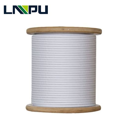
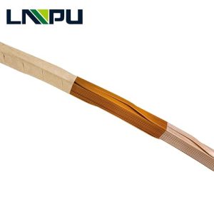
What is Paper Covered Conductor CTC Cable?
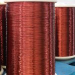
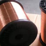
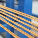
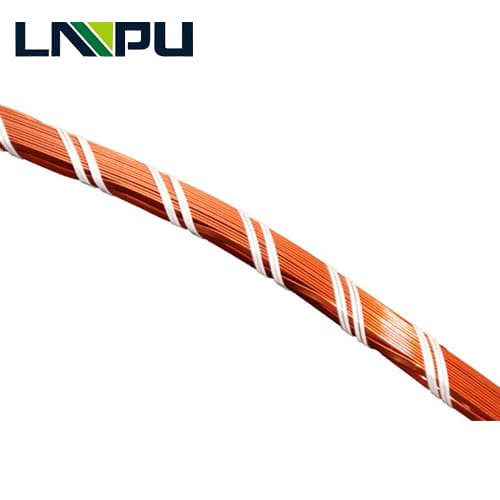
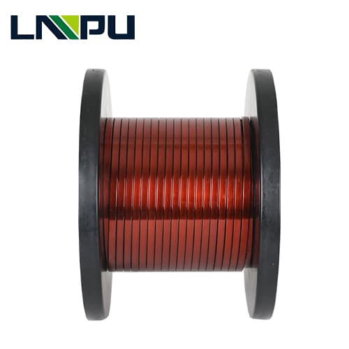
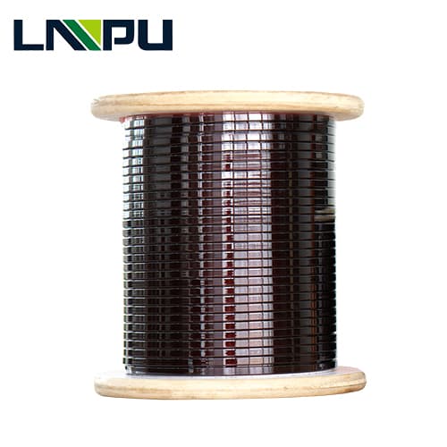
Paper Covered Conductor is one of CTC cable uses for high voltage transformer windings, substation windings, which consists of a number of rectangular,film insulated conductors made into an assembly and usually over-wrapped with layers of insulating material. The number of conductors is usually an odd number (from 5 to 81), arranged side by side in two stacks. A special tool alternately pushes the upper left and lower right wires onto the respective neighboring stack so that each wire takes on every possible position within one cycle in the continuously transposed cable. The length of the continuously transposed cable for one complete cycle depends on the smallest diameter of the transformer winding, the number and size of the single strip.
Why is Paper Covered Conductor CTC Cable the standard for high-voltage transformers?
Engineered for Ultra-High Dielectric Integrity & Low Load Losses
The substitution of single large rectangular wires by a Paper-Covered Transposed Strand Cable (PCTSC) actualizes a fundamental improvement in the efficiency of the transformer:
Tremendous Reduction of Eddy Losses ( P k) (inversion of numerous enameled rectangular strands passing continuously throughout the winding length)(no circulating currents):
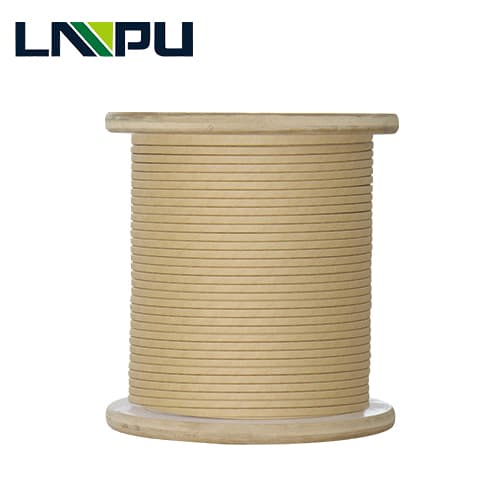
The transposed bundle is then wrapped with a high quality kraft or TUP paper. This paper will be vacuum-dried and transformer oil absorbed which provides an extremely high dielectric breakdown strength (> 70kV/mm).
Max. Short-Circuit Dynamic Stability: Optional B-Stage Epoxymoisture resistant coated strands form a single monolithic rigid block during factory vapor phase drying (VPD) or oven curing, which uses no coil deformation during short and immediately consecutive short circuits.
Optimized Winding Efficiency The controlled paper wrapping tension and uniform overlapping allow for tight dimensional tolerances, enabling automated transformer winding with less downtime, more automation, and higher production while saving time and money.
CTC Cable Techinical Specifications
| Parameter | Range (Metric) | Tolerance | Engineering Standard / Notes |
| Single Strand Thickness (a) | 0.90 – 3.15 mm | ± 0.010 mm | Single enameled conductor thickness |
| Single Strand Width (b) | 2.50 – 13.00 mm | ± 0.015 mm | Single enameled conductor width |
| Width-to-Thickness Ratio (b/a) | 2.0 ≤ b/a ≤ 9.0 | — | Optimized ratio to maintain strand stability during bending |
| Single Strand Enamel Coating | Polyvinyl Acetal (PVF) / PEI+PAI | Class 120 / Class 180 | Film thickness Grade 1 or Grade 2 according to IEC 60317 |
| Total Radial Paper Thickness | 0.30 – 3.00 mm | ± 0.030 mm | Customizable outer paper wrapping thickness |
| Max Bundle Dimensions | Height max: 120.0 mm Width max: 26.0 mm | ± 0.050 mm | Bundle size including outer paper insulation layers |
| Transposition number | 5 – 81 (odd or even optional) | – | – |
Paper Insulation Systems & Thermal Kinetics
Transformer lifespan depends on the degree of polymerization (DP) of the paper insulation.
Outer Paper Wrapping Options
High-Density Transformer Kraft Paper (IEC 60554-3-1 / Type 5.1):
Manufacturered from 100% unbleached sulfate wood pulp.
High tensile strength, low ash control, good oil-absorption rate.
Suitable for normal distribution and power transformers up to 220kV.
Thermally Upgraded Kraft Paper
(TUP – IEC 60554-3-5): Chemically nitrogened to cancel effect of the moisture and the organic acid degradation.
Enhance the transformer thermal endurance from 105°C of the operating temperature of the transformer to 120°C.
This effect lasts longer than 2000 h of the thermal overloading having a higher Degree of Polymerization (DP ≥ 1000).
Nomex® Aramid Paper / Micro-Creped Paper:
Design Class 220 for dry-type, trac- tion or high-temperature ester-filled transformers.
Provides Increased flexibility for short-radius winding heads.
Paper Wrapping ConfigurationsInterlocking
Half-Lap Wrapping (50% overlap): Maximum mechanical containment and dielectric strength.
Butt-Lap Wrapping (30%–47% overlap): Optimized oil path channels for enhanced cooling.
Quality Control & Laboratory Testing
In order to have a zero field failure of power transformer windings, all Paper Covered CTC drum passes 100% inline and offline test:
Monitoring values on transposition online: Strangely, detection of the laser sensor assured correct length of the pitch and dysfunctional defects in case of strand crossover.
Inter-Strand Dielectric Voltage Breakdown: 100% high-voltage continuity test across all neighboring strands (> 1000 AC/1s).
Degree of polymerization (DP) test: Raw paper DP of > 1100 is evaluated so that the winding assembly has a maximum lifetime.
Oil Impregnation & Moisture Test: Confirmed to ASTM D2413 as part of the verification of a total gas evacuation during transformer vacuum process.
Springback & Flexibility Test: Bending tests are performed on simulated winding mandrels with no tearing of paper or dislocation of strands.
Primary Application Scenarios
EHV / UHV Substation Transformers (330kV, 500kV, 750kV, 1000kV Grid Transformers)
Generator Step-Up Transformers (GSU) in Thermal, Hydro, and Nuclear Power Plants
High-Capacity Shunt & Series Reactors requiring extreme electromagnetic field stabilization
Traction & Industrial Furnace Transformers operating under severe mechanical impulse stress
Continuously transposed cable ctc Advantages
Transformers against unstable electrical network and the risks of shorts.
Conductors in the winding become like a solid beam and can withstand strong electrodynamic stresses created during short circuit event.
Copper with high mechanical characteristics (generally CPR with a proof stress 0.1% of 140 ÷ 250 MPa) – in order to withstand the electrodynamic stresses in case of short circuits.
Rectangular wires enamelled with polyvinylacetal enamels resistant to transformer oils. Epoxy coating over the enamelled rectangular wires (PVA‑EPOXY) – a thin layer of tack-free cresol-free epoxy B-stage that bond the strands together after the thermal treatment of the winding, getting a solid monolithic winding in order to withstand the electrodynamic stresses in case of short circuits.