
Summary
With the growth in worldwide power consumption, and the rapid increase in renewable generation renewable installed capacity expanded globally from 600 GW in 2015 to 3,800 GW in 2025 at an annual rate of 20% performance of power transformers is under unprecedented pressure. The conductor in the windings of every high-efficiency power transformer is fundamental to the performance, and LV copper CTC (Continuously Transposed Conductor) technology is now the accepted engineering standard for LV windings in power and distribution transformers.
CTC is not a new technology but it is quickly becoming more relevant. Initiative to modernize the grid, rising pressure on energy efficiency standards, and exploding growth in wind and solar power are all pushing transformer designers to work smarter by squeezing more power out of less material. Copper CTC delivers on all three metrics: it minimizes winding losses between 65-75% compared to traditional conductor designs, allows for a more small footprint transformer architecture, and performs reliably in the high-stress, fluctuating load driven by renewable energy sources.
This guide details precisely what the LV copper CTC technology is, how it works, why it‘s better than other solutions, and how the specifiers (engineers and transformer OEMs) can utilize it to harden their product designs.
Key advancements for low-voltage applications:
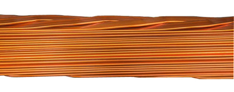
Unlike traditional round wires, LV Copper CTC comprises stacked thin rectangular copper strips (0.5–2mm thick) continuously transposed along the axis. Each strand is coated with high-temperature insulation (PVA or polyesterimide) and bonded with epoxy resin.
This precisely twisted assembly of insulated rectangular copper wires eliminates eddy current losses through periodic transposition, boosting efficiency in heavy electrical equipment by up to 15%.
CTC is essential for renewable energy transformers (wind, solar, traction) where high-current, variable-frequency loads greatly enhance standard winding losses.
Space Efficiency: 30% higher fill factor enables more copper in same space
Thermal Management: Insulation withstands 220°C (e.g., PolyFlex® 225) with crepe paper/Nomex tape wrapping
Mechanical Strength: B-grade epoxy boosts tensile strength by 40%, resisting operational vibrations
70% saving in winding losses for large power transformer by applying CTC instead of non-transposed conductors.
Specifications
| Parameter | S1215 | |
| 1|Winding type | HV | |
| Winding diameter | 1100 | mm |
| Number of strips | 13 | |
| Bare Width | 5.1 | Tolerance As per IEC |
| Bare Thickness | 1.1 | Tolerance As per IEC |
| Proof Stress | 140 | MPa |
| Enamel Coating- PVA | 0.08 | Tolerance As per IEC |
| 8|Epoxy | 0.04 | Tolerance As per IEC |
| 9|Type of Paper | Thermally upgraded | IEC 60664: 5A4-1M1 |
| Paper increase | 1.8 | mm |
| Intercolumn Paper | NA | |
| Radial Height | 10.2 | mm |
| Axial Width | 12.14 | mm |
| Length per drum | 9272 | m |
| No. of drums per unit | 2 | No.s |
| Total weight | 12503 | kg |
| Paper arrangement: Inner layers shall be butt lap without gap, staggering of approximately 30% Outer 2 layers shall be 50% interlocked |
||
What Is LV Copper CTC Technology?
Continuously Transposed Conductor (CTC) is a long multi-strand winding conductor used in the LV and high current windings of power transformers, autotransformers, reactors and traction transformers. It is formed of a number of rectangular enamelled copper strands (from 5 to 80 individual strands) which are stacked in an interleaved fashion in two two stacks and continuously transposed along their length.
The critical points are the transposition itself, every strand gradually and successively moves on the whole cross section of the cable surface. Once the transpositions is complete, every strand has carried each position in the bunch during a transpositor period. It would equalise the flux linkage of the magnetic flux of all the strands.
On the other hand, an un-transposed multi-strand conductor enables strands that have higher flux linkage positions to flow significantly higher circulating currents, leading to high heating and energy wastage resulting from load loss.
The finished CTC product is typically insulated in one of two ways:
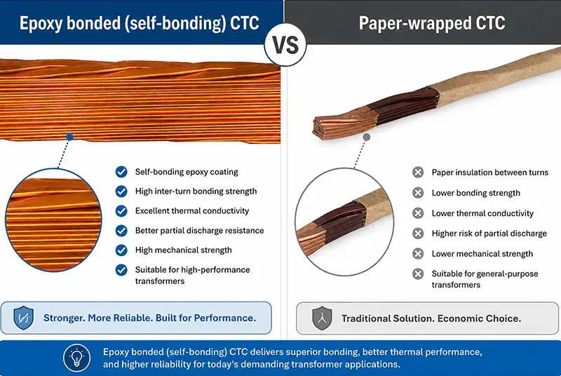
Paper-wrapped CTC: Outer insulation of cellulose kraft paper, thermo-stabilized paper, or aramid paper for higher thermal classes – the most typical insulation material for oil-immersed transformers.
Epoxy bonded (self-bonding) CTC strands coated with a thermally activated epoxy resin which, under heat during winding, bonds the assembly into a rigid, mechanically superior unit mainly used where high shortcircuit withstand strength is required.
Strand level individual strand enamels are generally polyvinylformal (PVF) in athermaldamp classes of 120 degreesC to 200 degreesC for strand widths of between 3.00 – 12.50 mm and thicknesses of between 1.10 – 3.15 mm.
How LV Copper CTC Works: The Engineering Mechanics
To establish why CTC is better than a regular conductor, we need to understand where the transformer losses occur in an LV winding.
Eddy Current and Circulating Current Losses Explained
When a multi-strand LV winding carries high currents, two distinct forms of stray loss emerge:
The eddy current loss is because of each individual conductor strand lying with in a variable leakage magnetic field. A voltage is induced in the cross-sectional area of the strand, causing a circulating current, dissipating power and hence loss at a rate proportional to the square of strand thickness, and square of the frequency.
Circulating currents are a similar effect. If two parallel strands in a winding are set at different radial heights, they will thread different quantities of leakage flux. This causes different EMFs in each strand, and in the absence of any external load, forces these to circulate around the parallel circuit by virtue of the electrical connection between the ends of the strands:
Stray and eddy current losses in large generator transformers, or high current LV windings, can constitute between 10 and 30% of the total resistive (I2 R) losses at these currents in normal operation and can even exceed 30% in furnace and rectifier transformers with very high LV currents.
How Transposition Eliminates These Losses
CTC addresses the issue at its source. When every strand completes a full cycle through all positions in the conductor cross section in one transposition pitch, the expected flux linkage to each strand averages out. There is same flux linkage to everyone, zero inter-strand EMF difference, and no circulating currents.
The practical benefit: CTC can eliminate winding losses in large generator transformers by as much as 75% over the typical un-transposed multi-strand conductor providing one of the largest single-component efficiency gains available in a transformer design.
Moreover, since the segments of cross-section can be smaller than the required cross-sectional area in a single large conductor, eddy-current within each single strand is minimized. By dividing large- cross-section conductor into many thin strand, the eddy current losses in each strands are minimized.
Space Factor and Thermal Benefits
The flexible nature of the two column winding of the CTC results in a high space factor, the percentage of conductive copper to total conductor cross-section. Keeping dielectric thickness to a minimum while ensuring dielectric strength is maintained will maximize the space factor, and thus increase the percentage of copper in the same winding window, allowing a transformer of a smaller overall size (for a given rating) or a higher rating to be constructed in the same size.
The additional advantage of the transposition design is the improved spread of heat. As all the currents are balanced across all their strands, it can operate at higher atmospheric temperatures whilst avoiding areas of concentrated heating which lead to localised insulation damage.
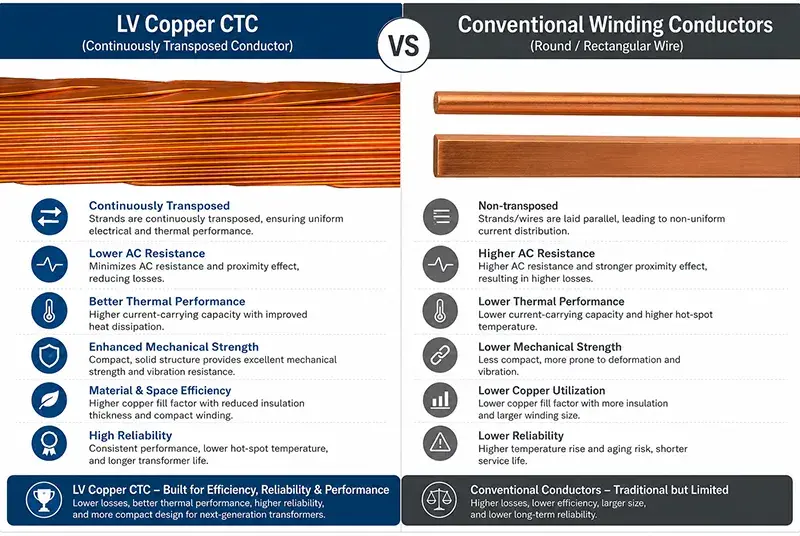
LV Copper CTC vs. Conventional Winding Conductors
Transformer designers typically choose between three conductor approaches for LV windings:
| Parameter | Paper-Insulated Copper (PICC) | Bunched/Parallel Conductors | Copper CTC |
| Eddy current losses | Moderate to high | Moderate | Very low |
| Circulating current losses | High (if untransposed) | Moderate | Eliminated |
| Winding time | Standard | Longer (manual transposition) | Faster (pre-transposed) |
| Space factor | Moderate | Moderate | High |
| Mechanical strengtd | Good | Moderate | Excellent (self-bonding type) |
| Short-circuit witdstand | Good | Variable | Excellent (epoxy-bonded) |
| Cost per kg | Lower | Moderate | Higher upfront, lower lifecycle |
| Mandated use (India CEA) | Below 400 A | — | Above 400 A |
Paper Insulated Copper Conductors PICC is still the standard choice for the smaller transformers such as lower current HV windings, medium voltage regulation windings and smaller distribution transformers. Its strength, demonstrated dielectric characteristics and also budget price compliment CTC in larger transformer designs.
Bunched/parallel conductors can provide equivalent performance, but will have to be carefully man-transposed manually by the winding team down on the factory floor this increases time, skill level and the chance of transposition error. CTC provides the transposition as a precisely manufactured semi-fabricated product, removing that variability completely.
CTC Manufacturing: What Specifiers Need to Know
The quality of a CTC conductor and the performance of the finished transformer are already decided long before CTCs are even shipped down the corridor to the winding floor. Critical manufacturing parameters have a direct influence on transformer performance and long term endurance.
Copper Purity and Rod Quality
The baseline raw material used is of high-conductivity copper usually ETP copper (Electrolytic Tough Pitch), conforming to ASTM B49 specification or its equivalent. Copper purity is significant because the electrical resistivity is increased proportionally by the impurity elements within the material at ppm levels. The International Electrotechnical Commission (IEC) determined the resistivity of commercial pure copper after annealing at 20 °C by 1.7241 cm (listed as 100% IACS, published 1913). Increased from this value will result in more I2 R losses in the winding.
The surface quality of the rod is just as important any deep oxide inclusions, edge burrs or surface cuts can punch through the insulator between the enamel, when transposed; causing inter-strand shorts and creating hot spots which will greatly speed-up the age of the insulator.
Enamel Insulation Integrity
Single strands are coated with insulating enamels (PVF are usual, or polyester/polyamide-imide for higher temperature class). The enamel coating must be even thickness and not eccentric. Eccentric coating of the strands (.e. marginal coating thickness in one place, thick in another) results in local electric field enhancement at the eccentric point, therefore reducing the Partial Discharge Inception Voltage.,2 In service, this leads to accelerated insulation failure.
Transposition Precision and Pitch Length
The transposition pitch the length over which a complete transposition cycle occurs must be specified within close tolerances. Transposition pitch lengths are typically between 35 and 225 mm for the various strand sizes, while the crossover length (the distance moved by the strand between the columns) is defined accurately by the strand width. An inappropriate pitch leads to incomplete flux equalisation, and largely defeats the objectives of the CTC.
Outer Insulation Options
CTC assemblies are covered with outer insulating wraps after transposition. Options include:
Kraft paper – cheap & has good dielectric properties and used for ordinary oil immersed transformer.
Thermo-stabilised paper: Thermo-stable at higher temperatures; important property for the use in transformers above the limit of the standard class thermal limits.
Aramid paper (e.g. Nomex): For use in dry-type or highperformance oil-immersed transformers for operation at a thermal class H (180 degrees C).
Micro-crepe paper: enhances flexibility when winding without causing cracking or delamination.
CTC in Renewable Energy Systems: Why It Matters Now
The worldwide energy transition will also represent a much different operating environment for the transformer winding conductors one they were never intended to operate in. And CTC‘s benefits do exactly this.
Wind Power Transformers
Offshore and onshore wind turbines are fitted with step-up transformers within the nacelle and pad-mount transformer located at the base to deliver power to the Medium-voltage collection grid. These transformers are:
Varying frequency loading as the turbine output changes, loss scale with square of frequency so that harmonic content at high frequency is much more damaging than at low in standard conductors.
With change in wind speed, cyclic thermal loading #thermal management inside the winding becomes critical to avoid hotspot degradation.
Tight installation dimensions NMT (nacelle mounted transformers) have extremely tight dimensional envelopes.
The capacity of the CTC to reduce eddy and circulating current losses at variable-load, along with its space factor advantage, favors the CTC as the conductor for high capacity wind transformer windings with above 400 A LV current.
Solar (PV) Farm Transformers
Utility-scale solar PV projects employ central inverter transformers (CITs) or pad-mounted distribution transformers to step up voltage from DC/AC conversion (600–1,500V) to medium-voltage levels compatible with the grid. Central inverter transformers (CITs) are:
Operate around the inverter harmonics causing high eddy current losses in winding conductors.
Often in situations where the cooling airflow is restricted (desert or arid climates) and temperature rise and management within the windings is important.
Must obtain very high efficiencies to optimize energy yields — even very small fractional increases in efficiency provide huge annual value to GW-size farms.
S&P Global estimates that globally, the installed solar PV capacity will rise to as much as 7,500 GW by 2040, up from 2,300 GW in 2024. Each GW demands collection, step-up and grid-interconnection transformers, with CTC in their LV windings providing the efficiency performance needed for project economics.
Grid Modernisation and Energy Storage
Grid-scale energy storage BESS requires bidirectional transformers connected between the storage‘s DC side and the AC power grid. These require frequent cycling at full load and need to withstand four-quadrant power flow. CTC‘s proven performance through charge/discharge cycling will be well suited to BESS installaions: low thermal cycling fatigue and performance consistency.
Specifying CTC for Your Transformer Design: Practical Guidelines
Getting the best out of CTC is achieved by matching the cone specification with the parameters of the transformer design.
Strand Count Selection
The number of strands in a CTC (generally 5 to 80: odd numbers are needed to support both E and G as the end-to-end transposition position in this geometrically-correct system) should be chosen according to:
LV winding current: Higher currents require increased number of strands to keep individual strand cross-sections acceptable and to reduce per-strand eddy losses.
Winding window geometry: the CTC height (5.50–70.00mm) and width (6.00–26.00mm) are within the dimensions of the available winding window and ensure the minimum number of required turns is obtained.
Pitch of transposition: Smaller pitch enhances flux equalisation but makes manufacturing more challenging; ratio of pitch to strand dimension is specified depending on application.
Quality Acceptance Criteria
When procuring CTC, specify and verify:
Edge burr 0.05 mm larger burrs etch through the enamel, and short circuits between turns.
Ename1 eccentricity 25% excessiv Ename1 variation increases partial discharge inception voltage.
Elongation at break 15% strands may experience cracking under tension during winding. Continuous length without joint 4,000 m means a joint presence in a winding and could be a reliability risk.
IEC 60317 or ASTM specifications of enamelled copper wire, IEC 60317-0-2 specifications for copper strip.
Frequently Asked Questions
Q: What does “LV” mean in the context of CTC transformer windings?
A: LV is “low” voltage and refers to the secondary of a step-up or step-down transformer generally the winding with the higher current at lower voltage. Because the current flowing in the LV winding of the transformer will be high, the effects of eddy current and circulating current losses are most apparent in this winding and the CTC winding conductor is used in LV coils of medium and large power transformers.
Q: How many wires does a standard copper CTC have?
A: Commercial copper CTC construct types range from 5to 81 individual rectangular enamelled strands. They are always odd so that geometrically correct transposition can occur, and at higher voltages it is desirable to have this as close to the winding as is practical. Typical configurations for large power transformer LV windings are often in the region of 20 47 strands. The number of strands is a function of current capacity, winding window dimensions and acceptable eddy current loss per strand.
Q: How does standard CTC compare with self-bonding (epoxy bonded) CTC?
A: C: Standard CTC is protected with paper-based outer insulation and depends upon the clamping arrangement of the transformer for mechanical support in handling the short-circuit force. Epoxy-bonded CTC (also known as epoxy resin impregnated CTC) has a layer of thermally activated epoxy coating on the strands which bonds the bunch into a dense composite during the manufacture of the transformer. Self-bonding CTC is significantly stronger in terms of mechanical strength and short-circuit withstand capability. It is suitable for generator transformers or other applications exposed to high levels of short-circuit fire.
Q: What makes CTC more critical in renewable energy applications?
A: Renewable energy transformers particularly those for use with wind and solar PV generation are subject to frequency and load variations that exacerbate classic winding losses. Wind turbine power transformer operation is characterized by rapid cycling of load conditions and harmonics that increase eddy current losses on untransposed conductors. Solar inverter transformer operation is subject to high harmonic distortion due to switching harmonics. The CTC transposition design prevents circulating currents and minimizes eddy losses, regardless of load profile, providing the ideal conductor material for dependable, high efficiency operation over the complete renewable generation cycle.