
Introduction:
Using the incorrect type or specification of enameled wire in your inductor or coil is arguably the most common error that results in higher than expected costs for an electromagnetic component. The type of wire used determines the DC resistance, AC losses, thermal survivability, winding density and reliability of the design, but many engineers take the easy route of using what happens to be on the shelf at the time or base their design upon a previous component.
This handbook eliminates the confusion. Whether you are selecting a high frequency LLC converter inductor, audio crossover choke, or toroidal filter coil, the best method is the same: define your electrical specifications first, add thermal and mechanical constraints, and then check it all against the necessary compliance standards. This next part takes you through each factor, providing you with definitive instructions so you can specify your enameled wire stress free.
What is enameled wire and why is it a critical part of good coil design?
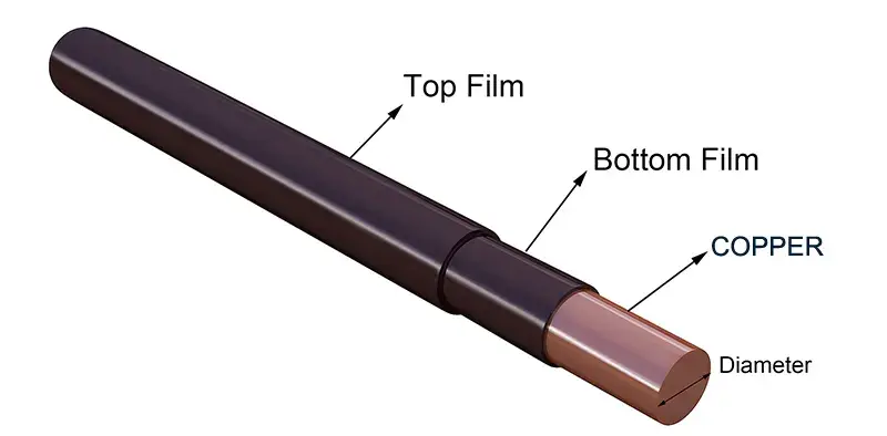
Enameled wire (also called magnet wire or winding wire) is an insulated single conductor made up of copper or aluminum. The conductor is covered by a fine layer of polymer film coating for turn-to-turn electrical insulation with no added bulk of traditional cable jackets. This enables highly dense windings needed by inductors, transformers, motors, and solenoids.
The enamel is not the vitreous glass coating the name suggests. Today‘s insulations are a setting of polymer resins called polyurethanes, polyesters, polyimide, polyamide-imide, polyimide, which are applied in multiple thin passes and heated in an oven. Each chemistry has their advantages/disadvantages with respect to being heated at a high temperature; thermal endurance (rating and flexibility), mechanical robustness, solderability and chemical resistance.
Two properties make enameled wire uniquely suited to coil winding:
A very slim, consistent insulation wall. Since neighbouring turns are separated by the inter-turn voltage (which is rarely more than a few volts in the majority of magnetics), the insulation wall can be measured in microns instead of millimeters. It also maximizes the copper fill, within a specific winding window.
Bond directly to the conductor. The polymer film forms a bond with the copper or aluminum, and remains intact in the bending and tension of high speed machine winding.
Knowing these basics is also the pre-requisite for every downstream choice of product to select.
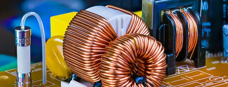
Wire Gauge Selection: Balancing DCR, Turns, and Current Capacity
Wire gauge, the choice of the one dimensional parameter that most factors into coil performance, is the most dominant dimensional parameter of a coil. In North America, much of the electronics industry, enameled wire is specified using AWG, or American Wire Gauge. This scale is based upon a logarithm, and a smaller number corresponds to a thicker wire. Other regions, such as IEC regions, specify millimeter diameter or cross-sectional area directly.
Current-Carrying Capacity and Current Density
The usual benchmark power electronics operation is about 3 A/mm2 with copper conductors. This gives a resistive heating level that is tolerable by nearly all wrapped components with convective cooling. For thermally constrained designs (sealed boxes, potted assemblies), 2 A/mm2 is a more comfortable ceiling. Forced air or liquids can go to 5–6 A/mm2.
To run at this in practice: Take the RMS inductor current and divide it by you current density to determine the minimum cross-sectional area needed, then look up the corresponding AWG size that has an area greater than or equal to that. Moving down three AWG sizes doubles the cross-sectional area of the conductor.
The Turns-Per-Layer Trade-Off
A heavier wire (lower AWG) has a higher current-carrying capacity but fewer turns of wire per length in the same winding window. A lighter wire (higher AWG) has a higher turn density in the same winding window but also has a higher DCR. Inductance increases quadratically with the number of turns; decreasing number of turns to make room for heavier wire applies a non-linear penalty on the achievable inductor inductance.
In most cases the power inductor design will end up on a gauge that meets the current requirement and has just enough turns to occupy the necessary winding window on the core (the available space for winding copper). The fill factor (usually 0.65–0.75 for round wire with random winding) must be considered in relation to the total winding window area. Never think 100% fill is realistic. In reality the voids in between round conductors take up 25–35% of the winding window area.
AWG Quick-Reference for Common Inductor Applications
| Application | Typical AWG Range | Notes |
| SMD power inductor (< 2 A) | 30–38 AWG | Fine wire; machine wound |
| Through-hole choke (2–10 A) | 20–28 AWG | Balance DCR vs. turns |
| High-current filter inductor (10–50 A) | 10–18 AWG | Consider foil or Litz above 50 kHz |
| RF resonant coil | 18–28 AWG | Silver-plated or Litz for Q > 50 |
| Audio crossover inductor | 14–20 AWG | Solid copper; low DCR priority |
Insulation Chemistry: Choosing the Right Enamel Type
The chemistry of the enamel influences six key characteristics that are essential to inductor and coil usage. Thermal class, solderability, chemical toughness and electrical and mechanical toughness are each impacted by the chemistry used. These can be divided into four broad families, which area covers most usage.
Polyurethane (PU) The Solderable Workhorse
The most common enameled wire insulator for consumer products, signal coils, relays and small inductors is polyurethane. Its only real benefit of selective soldering, which is that the vacuum insulation layer rapidly melts in molten 375-430 degreeC for no mechanical stripping of wire ends before soldering. This unique feature means it is that the polyurethane is widely used for ultra high volume manufacturing.
It is available in the standard Classes B, F and H of 130 degreesC, 155 degreesC and 180 degreesC respectively. The most commonly stocked grade is the 155 degreesC one (NEMA MW 79). A polyurethane-nylon version (NEMA MW 80) overcoats the polyurethane with nylon, giving some abrasion resistance which can be useful when making ferrite core coils with edges that can scrape off the bare polyurethane.
Polyester and Polyesterimide Thermal Durability
Polyester general insulation (Class F, 155°C) is higher quality than PU for thermal endurance and chemical resistance, but is not solderable. Widely used as a transformer & appliance motors where the parts are assembled by duct stripping or welding rather than soldering.
Polyesterimide (NEMA MW 30, Class H, 180 C) is another jump in performance consisting of modified polyester resins which aid withstand heat, good solvent resistance and a low coefficient of friction to assist winding speed on high speed machines. This type is used for more challenging industrial industors, HVAC compressor motors and servo drive components.
Polyamide-Imide (PAI) High-Performance Overcoat
Polyamide-imide is seldom found to be a field insulation but it does find application as a protection overcoat on polyesterimide films to give the Class 200 degreesC (Class C) insulation system. This two-coat construction frequently deemed “solderable H” in 180 degreesC grade delivers high thermal endurance, excellent mechanical toughness and very good freon, refrigerants and aggressive solvents resistance. It is used in refrigeration compressor motors and in high temperature inductor applications on automobiles and aircraft.
Polyimide The Extreme-Temperature Option
Polyimide enamel (Class H–C, 200–240 degreesC) is the crown jewel of the most demanding applications: military electronics, aerospace actuators, high-temperature oil and gas sensors, and automotive traction motor parts. It has the highest thermal capabilities, superb dielectric characteristics, and highest radiation resistance. The downside: it is more costly and it has the same snappability and stripability issues as Kapton– in other words, polyimide‘s can‘t be soldered without some nasty stripping chemicals
Temperature Class: Matching the Wire to the Thermal Environment
All enameled wire has a thermal class a maximum rated operating temperature at which the insulation will have a 20,000 hour service life according to the NEMA MW 1000 standard. The major classes and the each letter designation corresponding to each are:
| Thermal Class | Temperature (°C) | IEC Letter | Typical Insulation |
| Class 105 | 105°C | A | Plain enamel, Formvar |
| Class 130 | 130°C | B | Polyurethane (standard) |
| Class 155 | 155°C | F | Polyurethane-155, Polyester |
| Class 180 | 180°C | H | Polyesterimide, PU-180 |
| Class 200 | 200°C | N/C | PAI overcoat systems |
| Class 220+ | 220–240°C | C | Polyimide |
The biggest error engineers make is choosing a wire with a thermal class that is appropriate for the ambient temperature, but not accounting for the increased temperature caused by copper losses (I2 R heating). For a standard inductor operating at 40 degreesC in an ambient and 60 degreesC of internal temperature rise, the insulation needs to support 100 degreesC at the very least and many designers add a 20–30 degreesC derating to improve service life.
Calculate the thermal budget: ambient + winding temperature increase (from copper and core losses) + derating margin. Choose the thermal class greater than comfortably greater than this.
Copper vs. Aluminum: When to Use Each
Almost all inductors and coils are formed in copper. Its electrical conductivity (100% IACS) is about 60% better than that of aluminum (61% IACS), and a copper wire of specific cross-section can carry far more current at a much lower resistance.
For equivalent DC resistance, aluminum enameled wire needs a conductor cross-sectional area about 1.6x larger than copper. In practice this could be a heavier, larger-winding for smaller-to-medium inductor applications, eliminating the supposed space saving. Besides, aluminum has problems with solderability; it oxidizes easily and often needs special fluxes and termination techniques:
Aluminum makes sense in two scenarios:
Power transformers and large power inductors where the weight is important. Aluminum, with a density of 2.7 g/cm3 compared with copper at 8.9 g/cm3. For a large winding and are not constrained by size, the weight of windings can be greatly reduced.
Cost sensitive, high volume applications Aluminum wire can be purchased at a considerable discount compared to copper, and this may be important for consumer power supplies used at high volumes.
Copper enameled wire is the only feasible option for the huge majority of PCB mounted inductors, ferrite core filter chokes and RF coils.
Frequency Considerations: Skin Effect, Proximity Effect, and Litz Wire
In DC and low frequency, current flows uniformly through the mass of the conductor. However, as frequency rises, eddy currents generated by electromagnetic induction push this current towards the outside surface of the conductor; this ‘skin effect’ becomes more pronounced at higher frequencies, with the current penetrating less deeply as:
δ (mm) ≈ 66 / √f(Hz) for copper at room temperature
The skin depth in copper at 10 kHz is about 0.66 mm. A conductor with a diameter greater than about 2 sees will experience a significant rise of its AC resistance over its DC resistance. At 100 kHz it is about ( 0.21 mm), a wire of 26 AWG bare diameter 0.40 mm will have an increased AC loss.
The proximity effect amplifies this problem: an alternating magnetic field from a turn with a current in it causes eddy currents to form in the neighboring conductor. These eddy currents distort this wires current to oneshellcurrent.
When to Use Litz Wire
Litz wire (from the German Litzendraht, braided wire) solves both problems by building the conductor from many fine individually enameled strands twisted or braided so that over a specified length, every strand is at every radial position in the bundle, thereby sharing current equally. This keeps the current in each strand low enough for skin effect losses to be negligible.
The rule of thumb for practical decision-making: Use Litz wire if working at a frequency where the workin‘fcrossed the point where your conductor diameter has become greater than 2x the skin depth. Roughly:
| Frequency Range | Recommendation |
| DC to 10 kHz | Solid enameled wire is adequate |
| 10 kHz – 50 kHz | Evaluate — heavier gauges may need Litz |
| 50 kHz – 500 kHz | Litz wire strongly recommended |
| 500 kHz – 2 MHz | Litz with fine strands (38–44 AWG per strand) |
| Above 2 MHz | Litz benefits diminish; silver-plated wire or hollow conductors may be superior |
Notice that the interference line is on 1–2 MHz, thus Litz wire gets most advantages below it. Above this limit, the inter-strand capacitance appears and the bundle as a whole exhibits skin effect as a unit, reducing the benefit from efficiency gained from Litz wire. Silver-plated copper wire and air-spaced winding geometry usually gives a better choice when dealing MHz RF inductors.
Litz wire individual strands are insulated with the same enamel chemistries as found in magnet wire polyurethane chemistries dominate for their solderability; entire strand terminations can be tinned at once.
Self-Bonding Wire: Building Self-Supporting Coils
Self-bonding enameled wire receives a thermoplastic/thermoset coating (normally epoxy resin, polyvinyl butyral ‘PVB’, or polyamide) over the primary insulative film. Upon heat (at about 120–180 degrees C) or solvent (isopropyl or denatured alcohol in the PVB systems) application, this coating softens, fusing all neighboring turns, before the coil return to cool and become a rigid self supporting structure.
A self-bonding wire is the enabling technology for air-core coils, voice coils, bobbinless inductors and any winding that needs to hold its shape without mechanical aid. The bonding can be:
Bake the wound coil in the oven at the bonding temperature for:
The flow of current through the winding to produce I2 R heat in the place
Solvent application (for alcohol-activated grades) using the coil on a mandrel
The base insulation thermal class is not affected by bonding: a Class F polyurethane bondable wire still has the 155 degrees C rating after activation. Choose the bondable grade to match the base insulation thermal class needed for the application.
Winding Geometry and Coil Construction: Use wire choice for various inductor types
The type of wire used cannot be set completely independently of the winding geometry it must fit.
Toroidal Inductors
Toroids offer low leakage flux and small size, but toroidal windings are made either by hand or on a shuttle-winder which put relatively large bending stress on the wires. This is an important consideration-the tougher the insulation material such as polyimide or thick polyesterimide, the greater the crack at very small bend radii for thinner wire gauge. For ring-wound toroids, the polyurehane and polyurehane-nylon grades with good bend radii are used. Litz wire for toroids are possible but adds to the difficulty of all the termination points.
Bobbin (E-Core, Pot-Core) Inductors
Bobbins allow high speed machine winding. Abrasion resistance may be important as the wire drags over the flanges on the bobbins, in this case a polyurethane-nylon overcoat (NEMA MW 80) or polyesterimide outperforms plain polyurethane. For high-voltage layer wound designs, an extra (polyester-tape) may be used as an inter-layer insulation to complement the turn-to-turn insulation of the wire.
Air-Core RF Coils
Air-core inductor with high-Q for RF and resonant circuits require to be very low dielectric losses and dimension critical tolerance Silver-plated copper wire (where the silver surface is so thin that it reduces the resistive loss at MHz), Litz wire or fine-strand Litz wire are the best options. The self-resonant frequency SRF of the coil (determined by the inter-winding capacitance) should be well above frequency of operation. Stretched or spaced (non-close-wound) winding methods are used to reduce inter-turn capacitance as well as SRF.
SMD Chip Inductors
As for the chip inductor level, winding is an automated machine process with fine wire down to 44 AWG or less. Insulation must pass into extremely high speed and high tension winding without cracking, and the thermal class must allow for reflow soldering profile (peak temperatures of 250 260 degreesC for SAC305 solder). Polyurethane-180 (direct solderable at reflow temperatures) or polyestermide grades with mechanical stripping at the terminations are standard.
Insulation Build: Single, Heavy, and Triple Coatings
In addition to the chemistry of the insulation, the insulation build (the thickness of the coating) influences the outer diameter of the completed wire and also its dielectric withstand voltage. IEC 60317 and NEMA MW 1000 specify standard build grades:
Single Build (Type 1): Minimum coating thickness. Offers the most turns per unit winding area. Works well when inter-turn voltages are low (signal coils, low-voltage power inductors).
Heavy build (Type 2): ~40% thicker than single build. The most popular general purpose option for power inductors — a little more resistant abrasion, a high withstand dielectric, only modest reduction of turns density.
Triple Build (Type 3): Mainly for high voltage scenarios, layer-wound transformers, and where turn-to-turn or layer-to-layer voltage exceeds normal insulation levels.
As for any wire gauge, heavy build wire has a slightly larger diamter than single build a small reduction in maximum turns per layer. Both inductor design software and component supplier data sheets give the outer diameter of all build grades.
Quality Standards and Compliance
A insulation chemistry and thermal class must be specified, but is not enough. Once it has been proven that the wire conforms to a published specification, all tolerances and electrical performance levels are defined along with the consistency of purchase.
The North American specification used most commonly is NEMA MW 1000. It stipulates the thermal class, type of insulation, dimensional tolerances and test methods applicable for each wire designator (i. E. MW 79 is used to specify polyurethane-155). The NEMA “MW” number is the most common abbreviation used by most purchasing departments and suppliers.
IEC 60317 is the corresponding worldwide standard. It is categorized by type of insulation and temperature class. Suppliers based in Europe and Asia specify their product using IEC designations. If you are buying from anywhere in the world, check if your supplier is certified for NEMA MW 1000, IEC 60317, or both.
UL recognition is necessary, as the end product may not carry recognition unless the UL component is also recognized. The wire used in recognized inductors has UL 1446 (system of insulation material) or similar UL recognition.
Service life for the rated thermal class is 20,000 hours at continuous rated temperature (NEMA MW 1000). The derating of wire temperature that reflects operating 20-30 degreesC below the rated class greatly benefits service life and is essential when part of long-life applications such as those in the industrial or automotive realm.
Practical Wire Selection Checklist
Use this checklist before placing a wire specification:
Electrical requirements: RMS current -> minimum cross-section of the conductor at 3 A/mm2 (or adjusted for thermal environment) -> AWG choice
Turns requirement: Target inductance + core area -> turns required -> check that it will fit in winding window at selected AWG (0.65 – 0.70 fill factor)
Frequency: Above 20-50 kHz?-> evaluate Litz wire. Above 1 MHz?-> evaluate silver-plate or spaced winding
Thermal budget: Ambient + I2 R rise + derating margin -> thermal class
Insulation chemistry: soldereability required? -> polyurethane High abrasion? -> nylon overcoat. Extreme temperature? -> PAI or polyimide
Self-supporting coil?-> State bondable grade.
Insulation build; low voltage, max turns -> single build. General purpose -> heavy build. High voltage -> triple build.
Standards: Confirm NEMA MW 1000 or IEC 60317 designation. Is UL recognition required?
Dimensional: Drilled hole in the pole (abrasion priority) vs. Non-drilled stationary pole (collapsing flexibility priority) vs. Box pole (dimension flexibility). Propagation: Toroid (dimensional flexibility vs. abrasion).
Frequently Asked Questions
Q: What‘s the different? Single build/heavy build enamaled wire
A: Thickness of the insulation coating. A single build (Type 1) application utilizes the minimum coating thickness specified, providing the maximum turn count per layer at the lowest inter-turn voltages. A heavier build (Type 2) is roughly 40% thicker, providing greater abrasion resistance and higher dielectric withstand, and is the standard in most power inductor designs. A triple build (Type 3) is for high voltage windings. These three variations all exist within the same insulation chemistry and thermal class.
Q: How many kHz should I install the transition from solid enameled wire to Litz wire?
A: A rule of thumb would be where the conductor diameter is greater than 2 times skin depth at the frequency of operation. This would be about 20–50 kHz for copper for standard power- inductor sizes (20–28 AWG). Above this the AC resistance of a solid conductor wire begins to become measurably higher than the DCR. Above 50 kHz the Litz wire provides material efficiency benefits. Above 1–2 MHz the net benefits of using Litz wire diminish due to the effects of inter-strand capacitance and then silver plated wire or other techniques become necessary.
Q: What about using polyurethane enameled wire for reflow-soldered SMD inductors?
A: Polyurethane-155 and polyurethane-180 grades are directly solderable the enamel will wash off with molten solder, making termination easier. However, standard polyurethane-155 is rated to 155 deg C while SAC305 leadfree reflow peaks at 250-260 deg C. For SMD inductors going through reflow specify polyurethane-180 or check with your wire supplier that the grade has been proved for reflow soldering profiles. Always check solderability with your production solder profile.
Q: Self-bonding enameled wire has a modified coating compared to normal enameled wire. What is it?
A: Self-bonding wire features a co-polymer superimposed co-polymer coating which over folds or layers when heated by solvent softening. This feature allows turns to stick together and bond on warming to form a stiff, self supportive wound coil construction; no bobbin, potting material or fixings are needed in many applications .. resulting in a lighter smaller component. This construction is ideal for air core inductors, voice coils and portable equipment coils.
Q: How do you explain why the cross-section of an aluminum enameled wire has to be larger than copper for the same application?
A: Aluminum has about 61% of copper‘s [ IACS] electrical conductance. To make the same DC resistance in a winding as a copper conductor, the aluminum conductor would need to have about 1.6x the cross sectional area of that copper conductor. This too usually means a much larger outside diameter (hence lower AWG equivalent) which means fewer turns in the same winding window and often cancels out the weight/cost benefits aluminum has. Copper is still the material of choice for small-to-medium inductors.
Q: How do the NEMA MW numbers for magnet wire specifications translate?
A: NEMA MW numbers (for example, MW 79, MW 80, MW 30) are represented by a numbers/letter alphanumeric, established in the NEMA MW 1000 standard that precisely designate a combination of insulation type, thermal class, and dimensional build. (for example, MW 79 is single or heavy build polyurethane-155 insulation, with MW 80 adding the nylon overcoat to the polyurethane-nylon-155). When referencing an MW number in a wire specification or purchase order, you specify a wire that conforms to the thermal class, dimensional tolerances, and test requirements specified by the standard- which is important when taking different wire suppliers into account.
Conclusion
Choosing enameled wire for an inductor / coil is an engineering problem, not a catalog exercise. It begins with the electrical constraints (current density, turns count, DCR budget), then adds thermal, frequency and mechanical constraints, and results in an insulation chemistry, gauge, build and compliance designation.
All of these specification errors neglecting AC loss effects at high frequency, under-rating the thermal class relative to measured winding temperature, assuming a fill factor value without calculation are easily prevented using the methodology presented here. Use the selection checklist for all new designs, and correlate performance targets to the appropriate NEMA MW 1000 or IEC 60317 requirements prior to issuing specifications for production wire.
In the case where you are scaling from prototype to series volume, involve the wire vendor as early as possible: specialty grades (high-temperature polyimides, Litz constructions, bondable wire in fine gauges) can have long lead times, and agreeing upon dimensional tolerances up-front will save you a headache in winding yield issues at a later stage.