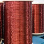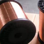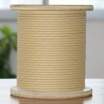
IEC 60317-0-7 is an international standard for fully insulated (FIW) non-defective enameled round copper wire. This standard specifies in detail the manufacturing requirements (these requirements cover the mechanical properties, electrical properties and environmental adaptability of the wire to ensure excellent performance under various conditions of use), performance tests and application areas of these wires to ensure their reliability and safety in electrical and electronic equipment.
Main Specifications of Manufacturing Requirements and Performance Tests
1. Insulation Performance
Fully insulated (FIW) enameled wire emphasizes the integrity of the insulation layer and requires no insulation defects (such as pinholes, bubbles, etc.). This ensures that the wire has excellent insulation performance under high voltage conditions to prevent current leakage and short circuits.
—Pinhole test: The insulation layer must undergo a rigorous pinhole test to ensure that there are no tiny defects. For example, the standard stipulates that the number of pinholes in enameled wire per 100 meters of length should be zero.
—Dielectric strength: The insulation layer should be able to withstand high voltage without being broken down, and the dielectric strength is usually required to reach 5000 V/mm or more.
2. Mechanical Properties
In terms of mechanical properties, IEC 60317-0-7 requires the wire to have high strength and ductility to ensure reliability during processing and use.
—Tensile strength: The wire must have sufficient tensile strength, usually above 200 N/mm², to withstand tensile and bending stresses.
—Ductility: The enameled wire needs to have good ductility, and the elongation is usually required to reach more than 20% to ensure that it will not break during winding and installation.
3. Thermal Performance
Fully insulated enameled wire must be able to work stably in high temperature environments without performance degradation.
—Thermal grade: The standard specifies different thermal grades (such as 130, 155, 180, etc.), which indicate that the wire can work for a long time at the corresponding temperature without significant aging.
—Thermal shock test: The wire must pass the thermal shock test, such as keeping it at 200°C for 72 hours, and the insulation layer must not crack or peel off.
4. Electrical Properties
In addition to insulation performance, IEC 60317-0-7 also specifies the conductivity and resistance requirements of enameled wire to ensure that it has low loss and high efficiency when transmitting current.
—Conductivity: The conductivity of the wire must meet the conductivity of international standard copper, usually requiring 58 MS/m or more.
—Resistance: The resistivity of the wire should be within the specified range to ensure that no excessive heat is generated under high load.
5. Environmental Adaptability
IEC 60317-0-7 also specifies the adaptability test of enameled wire under different environmental conditions, including moisture resistance, chemical resistance and weather resistance.
—Moisture resistance: The wire must pass the high humidity environment test to ensure that there is no performance degradation under humid conditions.
—Chemical resistance: The enameled wire must be able to withstand certain chemical corrosion, such as acids, alkalis and solvents, to ensure performance in complex industrial environments.
—Weather resistance: The standard also requires that the wire remain stable under UV and other climatic conditions without significant aging.
Test Requirements for FIW
- Dimensions
Dimensions of enameled wires for grade FIW 3,5,7,9
| Nominalconductordiameter | Conductortolerance | Minimum overall diametermm | Maximum overall diametermm | ||||||
| mm | amm | Gradeof FIW 3 | Gradeof FIW 5 | Gradeof FIW 7 | Gradeof FIW 9 | Gradeof FIW 3 | Gradeof FIW 5 | Grade ofFIW 7 | Grade ofFIW 9 |
| 040.0 0,045 0,050 0.056 0,063 | 0,055 0,062 0,067 0.075 0,084 | 0.070 0.079 0.084 660.0 0.103 | 0600 0,101 0,106 0,117 0.129 | 0.058 0,066 0.072 0,081 0600 | 0.079 0.089 960.0 0,104 0,115 | 660.0 0,111 0.116 0.128 0,141 | |||
| 0,071 0,080 0600 0,100 0,112 | 0,003 0.003 0.003 0.003 0.003 | 0.092 0,102 0,114 0,126 0,140 | 0,111 0.123 0,135 0,149 0,165 | 0,137 0,151 0,163 0,181 0.199 | 0,163 0,179 0,191 0.213 0,233 | 0,098 0,108 0.120 0,132 0,147 | 0.123 0.136 0,148 0,164 0,181 | 0.149 0,164 0.176 0.196 0,215 | 0,175 0.192 0,204 0,228 0,249 |
| 0.125 0,140 0,160 0.180 0,200 | 0.003 0.003 0.003 0.003 0.003 | 0.155 0,172 0.195 0,218 0,240 | 0,182 0,202 0.228 0,254 0.278 | 0,218 0,242 0,272 0,302 0,328 | 0,254 0,282 0,316 0,350 0,378 | 0,163 0,181 0.205 0,229 0,252 | 0,199 0,221 0,249 0,277 0,302 | 0,235 0,261 0.293 0.325 0,352 | 0,271 0,301 0.337 0,373 0,402 |
| 0,224 0,250 0,280 0,315 0,355 | 0.003 0,004 0,004 $00.0 0,004 | 0,267 0,298 0,330 0,368 0,412 | 0,308 0,343 0,377 0,416 0,460 | 0,362 0,403 0,439 0.478 0,522 | 0,416 0,463 0,501 0,540 0,584 | 0,280 0,312 0,345 0,384 0,428 | 0,334 0,372 0,407 0,446 0,490 | 0,388 0,432 0,469 0.508 0,552 | 0,442 0,492 0,531 0,570 0,614 |
| 0,400 0,450 0,500 0,560 0,630 | 0.005 0,005 0.005 9000 900 0 | 0,460 0,514 0,567 0,631 0,705 | 0,510 0,565 0.629 0,695 0,770 | 0,572 0,627 0,711 0,777 0.852 | 0,478 0,533 0.587 0,653 0,728 | 0,540 0,595 0.669 0,753 0,810 | 0.602 0,657 0,751 0,817 0,892 | ||
| 0.710 0090 0060 1,000 1.120 1.250 1,400 1,600 | 0.007 0,008 6000 010.0 0,011 0.013 0,014 0,016 | 0.790 0.885 0660 1.095 1,218 1,350 1,503 1,707 | 0.856 0,963 1.070 1.176 1,310 1,443 1,597 1,802 | 0.938 | 0,814 0,911 1,018 1,124 1,248 1,381 1,535 1,740 | 0,896 1,013 1.120 1,226 1,370 1,503 1,657 1,862 | 0.978 | ||
Dimensions of enameled wires for grade FIW 4,6,8
| Nominalconductordiameter | Conductortolerance | Minimum overall diametermm | Maximum overall diametermm | ||||
| mm | 1mm | Grade ofFIW 4 | Grade ofFIW 6 | Grade ofFIW 8 | Grade ofFIW 4 | Grade ofFIW 6 | Grade ofFIW 8 |
| 0.040 0,045 0.050 0,056 0,063 0,071 0,080 060.0 | 0.003 0,003 0.003 | 690.0 0,067 0.073 0,082 0600 0,098 0,109 0.121 | 0800 0600 S600 0,105 0.116 0,124 0,137 0.149 | 0,100 0,112 0,117 0.129 0,142 0,150 0,165 0,177 | 690’0 0.078 C8o.0 0,092 0,102 0,110 0,122 0,134 | 0,089 0,100 0,105 0,116 0.128 0,136 0,150 0.162 | 0,109 0,122 0,127 0,140 0,154 0,162 0,178 0.190 |
| 1,000 1.120 1,250 1,400 1,600 | 0,010 0,011 0,013 0,014 0,016 | 1.125 1,249 1,382 1,536 1,741 | 1,227 | 1,175 1,309 1,442 1,596 1,801 | 1,277 | ||
2. Electrical Resistance
| Nominal conductordiametermm | Resistance0/m | |
| Minimum | Maximum | |
| 0,040 0,045 0,050 0,056 0.063 | 12,280 9,705 7,922 6,316 5,045 | 14,920 11,790 9,489 7,565 5,922 |
| NOTE 1 The limit values shown in Table 3 are derived from calculations madeaccording to IEC 60317-0-1:2013, Annex B.NOTE 2 For the nominal resistance,see IEC 60317-0-1:2013,Annex C. | ||
3. Elongation at Break
| Nominal conductordiametermm | Minimum elongation atbreak% |
| 0,040 0,045 0900 0.056 0.063 0.071 0900 0600 | 9 9 10 10 12 13 14 15 |
| 1,000 1.120 1,250 1,400 1,600 | 30 30 31 32 32 |
4. Springiness
Springiness for grades FIW 3,5.7,9
| Nominal conductordiametermm | Mandreldiametermm | TensionN | Maximum springback | |||
| Grade ofFIW 3 | Grade ofFIW 5 | Grade ofFIW 7 | Grade ofFIW 9 | |||
| 080.0 0600 0,100 | 5.0 | 0.25 | 100 94 90 | N/AN/AN/A | N/AN/AN/A | N/AN/AN/A |
| 0,112 0.125 0.140 | 7.0 | 0.50 | 88 84 79 | N/AN/AN/A | N/AN/AN/A | N/AN/AN/A |
| 0,160 0.180 0,200 | 10.0 | 1.00 | 7 75 72 | N/AN/AN/A | N/AN/AN/A | N/AN/AN/A |
| 0,224 0,250 0,280 | 12.5 | 002 | 68 65 61 | N/AN/AN/A | N/AN/AN/A | N/AN/AN/A |
| 0,315 0,355 0,400 | 19.0 | 4.00 | 62 59 55 | N/AN/AV/N | N/AN/AN/A | N/AN/A |
| 0,450 0,500 099.0 | 25.0 | 8.00 | 53 51 48 | N/A7368 | N/A0688 | |
| 0,630 012.0 008.0 | 37.5 | 12.00 | 53 50 46 | 757165 | N/AN/A | |
| 0060 1,000 1.120 1,250 1,400 009.7 | 50.0 | 15.00 | 51 47 43 39 36 32 | 96 90 84 78 72 65 | ||
Springiness for grades FIW 4,6,8
| Nominalconductordiametermm | Mandreldiametermm | TensionN | Maximum springback | ||
| Grade ofFIW 4 | Grade ofFIW 6 | Grade ofFIW 8 | |||
| 090’0 0600 | 5.0 | 0.25 | N/AN/A | N/AN/A | N/AN/A |
| 1,000 1.120 1,250 1,400 1,600 | 0.09 | 15.00 | 65 60 54 50 45 | N/A | |
5. Mandrel winding test
Mandrel diameters for mandrel winding test for grade FIW 3,5,7 and 9
| Nominal conductordiametermm | Grade of FIW 3 | 0%elongation before winding | ||||
| Grade ofFIW 5 | Grade of | Grade ofFIW 9 | ||||
| Over | Up to andIncluding | Elongationbeforewinding% | Mandreldiametermm | Mandreldiametermm | Mandreldiametermm | Mandreldiametermm |
| 090.0 C90.0 0800 0600 0,140 0,200 0,355 0,450 0,710 006 0 1,000 | 0,050 0.063 0,080 0600 0,140 0,200 0,355 0,450 0,710 0,900 0000 1,600 | 20 15* 10 5 0 0 0 0 0 0 0 0 | 0,150 0.150 0,150 0,150 0,150 8 8 8 8 8 8 | 0020 0020 0,200 000.0 0,300 1-■ 1- 1x■ 3x 3x 3x■ 3x■ | 0,200 0,200 0,200 000.0 0,300 2- 2- 2x■ 4x■ | – 0,200 000.0 000.0 3x 3x |
| Or to the breaking point of the copper conductor,whichever is less.· df is thenominal diameter of the wire. | ||||||
Mandrel diameters for mandrel winding test for grade FIW 4, 6 and 8, nominal conductor diameters up to and including 0,090 mm and over 0,900 mm
| Nominal conductor diameter | Grade of FIW 4 | 0%elongation before winding | |||
| mm | Grade of FIW 6 | Grade of FIW 8 | |||
| Over | Up to andincluding | Elongationbeforewinding% | Mandreldiametermm | Mandreldiametermm | Mandreldiametermm |
| 0,050 C900 0.080 | 0.050 0.063 080.0 060 0 | 10 10 S 0 | 0,200 0,200 0.200 0,300 | 0,200 0.200 0,200 0000 | 0,200 0.200 0.200 0,300 |
| 0060 1,000 | 1,000 1,600 | 0 0 | 2x■ 8-2 | 4x – | – |
| Or to the breaking point of the copper conductor,whichever is less.d is the nominal diameter of the wire. | |||||
6. Heat shock
Heat shock for grades FIW 3, 5, 7 and 9
| Nominal conductordiametermm | Mandrel diametermm | |||
| Overall diameter range | ||||
| Grade ofFIW 3 | Grade ofFIW 5 | Grade of | Grade ofFIW 9 | |
| 0,160 0,180 0,200 0,224 0,250 | 0,250 0,280 0.315 0,355 0,400 | 0,450 0.450 0,450 0690 0,630 | 0,560 0,560 0990 0080 0,800 | 0,560 0.560 0.560 0001 0001 |
| 0.280 0,315 0,355 0,400 0,450 009.0 | 0090 0,710 0,800 0060 000.1 1.120 | 0090 1,000 1,000 1,000 1.120 1.120 | 0080 1,250 1,250 1,250 0002 0000 | 1,000 1.600 0091 |
| 0,560 0,630 0,710 0,800 0060 | 1,250 1,400 0091 1,800 0002 | 1,400 2,000 000.0 3,550 5,000 | 0002 2,800 2,800 | |
| 1,000 1.120 1,250 1,400 1,600 | 2,240 3,550 4,000 4,500 5,000 | 0000 0009 5,000 5,600 6,300 | ||
Heat shock for grades FIW 4, 6 and 8
| Nominal conductordiametermm | Mandrel diametermm | ||
| Overall diameter range | |||
| Grade of FIW 4 | Grade of FIW 6 | Grade of FIW 8 | |
| 0001 1,120 1,250 1,400 1,600 | 4,000 0009 0000 4,500 5,000 | 0009 0009 | |
7. Breakdown voltage
| Nominal conductordiametermm | Minimum specific breakdown voltageVium | ||
| Over | Up to andIncluding | Room temperature | Elevated temperature |
| – | 0.100 | 81 | |
| 006.0 | 0091 | 47 | 33 |
| NOTE The specific breakdown voltage is the result of the quotient of the measuredbreakdown voltage and enamel increase. | |||